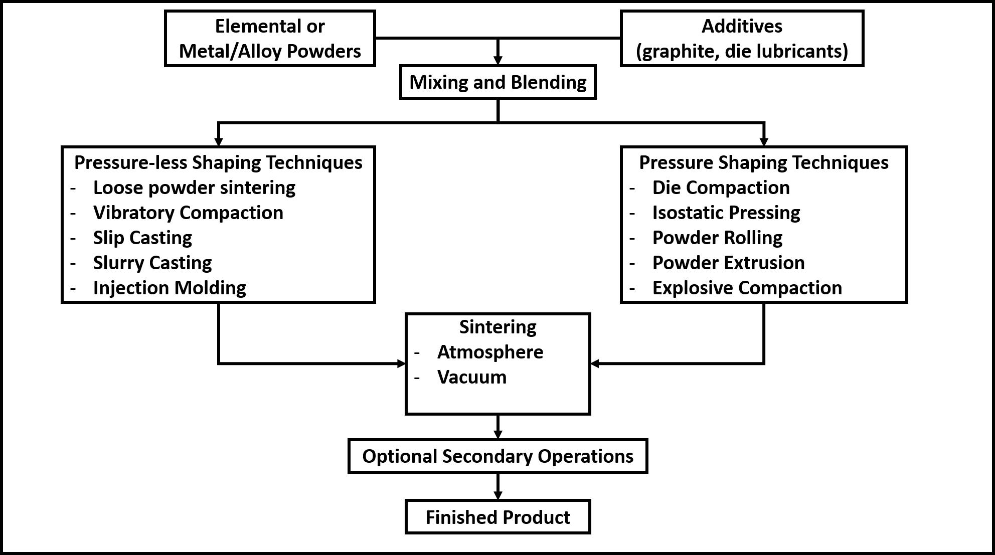
Steps involved in powder metallurgy process
-
Preparation of metal/alloy powders
The characteristics of the metal powders used in powder metallurgy for producing articles are crucial as they directly affect the properties of the finished products. The powder characteristics such as degree of purity, size, shape and distribution, are themselves dependent on the method of powder synthesis. The essential techniques for powder production are – milling, atomization and electrodeposition. Read more... -
Mixing and blending
Mixing: When two powders of different chemistries such as elemental powder mixes or metal-nonmetal powders are combined, it is known as mixing. This process may be done in either dry or wet conditions. A liquid medium like alcohol, acetone, benzene, or distilled water are use milling medium in wet milling. Ball mills or rod mills are utilized for mixing hard metals such as carbides.Read more... -
Compaction
Pressure-less shaping techniques: These are used for the production of low-density and simple parts such as filters and other components that are porous. These techniques do not use any external force and depend on gravity for powder packing. Read more... -
Sintering
Sintering is the process of heating the powder compact to elevated temperatures but below their melting point such that powder particles coalesce into a solid due to diffusion, not due to melting. Sintering is performed in order to impart strength and integrity to the powder compact, to remove porosity, and to increase the degree of densification. Read more...
- Preparation of metal/alloy powders
The characteristics of the metal powders used in powder metallurgy for producing articles are crucial as they directly affect the properties of the finished products. The powder characteristics such as degree of purity, size, shape and distribution, are themselves dependent on the method of powder synthesis. The essential techniques for powder production are – milling, atomization and electrodeposition.
Milling: This is the cheapest method to produce powders, and it is performed to reduce particle size, changing particle shape and for mechanical or solid-state mixing. Milling operation employs different types of forces such as impact, attrition, shear, and compression. Impact is the striking of one powder particle against another particle, resulting in size reduction whereas attrition is the production of wear debris due to friction as a result of rubbing action between two particles. Shear refers to the cutting of particles due to unaligned forces pushing different parts of the particle in different directions and compression is the squeezing action, resulting in fracture of coarser particles into fines. Milling equipments are classified as crushers and grinders.
Crushing is the initial stage of comminution in mineral processing and the primary objective is to achieve the desired size range for the next step, which is grinding. The size reduction is achieved using a combination of heavy-duty mechanical crushers and screens to pulverize, classify and recirculate the material. Crushing is usually a dry process and performed in various stages. It is performed using jaw crushers, gyratory crushers, cone crushers, high-pressure roll and impact crushers. Grinding is the stage following crushing, where the size reduction of already crushed particles occurs by the free motion of unconnected media. Unlike crushing, grinding can be performed in both dry and wet conditions.-
Roller mill
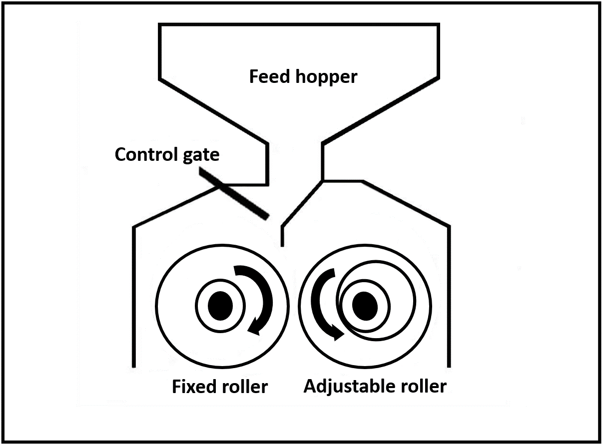
Roller mills use cylindrical rollers, either in opposing pairs or against flat plates to crush or grind various materials. Roller mills are typically used in mining and processing industries for treating ores and construction aggregates, cement milling and recycling.
Roller mills reduce particle size by shear and attrition. These forces are imparted by a set of rotating wheels moving at different speeds in opposite directions. The particle morphology is affected by the gap between the rolls, the speed of the rolls and the material feed rate.
Roller mills have certain advantages as the material produced is more uniform in terms of product quality with lesser fines and oversized products. These mills consume less energy and have low machine noise. However, roller mills are not effective for fibrous products and the operator inputs are frequently required as the rollers need to be adjusted to suit the grinding requirements.
-
Ball mill
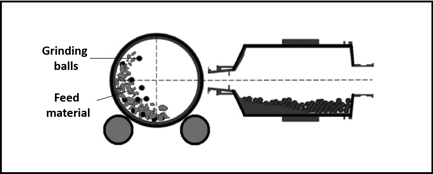
A ball mill works on the principle of impact and attrition. A ball mill consists of a hollow cylindrical shell rotating about its axis and this cylinder is partially filled with coarse material feed and grinding medium. Different materials are used as grinding media, including ceramic balls, flint pebbles and stainless steel balls. The inner surface of the cylindrical shell is lined with an abrasion-resistant material to prevent wearing and chipping of the surface.
Due to the rotation of the cylinder, the grinding media falls on the feed from a certain height which results in the size reduction of the feed material. Besides grinding, ball mills are extensively used in mechanical alloying process, i.e., cold welding. The key properties of the grinding media in determining the final product are size, density and hardness of the balls. Smaller the grinding media, smaller is the size of the final product. However, the size of the grinding media should be larger than the largest piece to be ground. Also, the grinding balls should have higher density than the material feed to prevent them from floating on top the feed material and the balls should have high hardness to ensure durability and prevent wearing of the balls during the grinding process.
Ball mill produces powders with very fine particle size, and the process can be made continuous. Ball milling is especially suitable for milling abrasive materials and this process allows wet grinding, which results in approximately 30% lesser power consumption as compared to dry grinding.
-
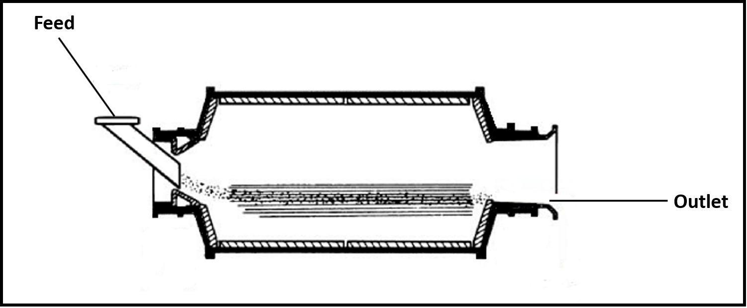
Tube mill
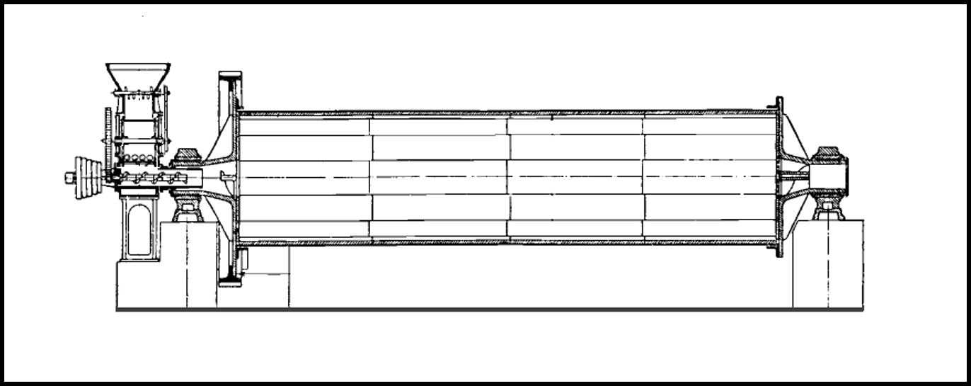
Tube mills consist of revolving cylinders, with a number of hard balls which act as the grinding media. Tube mills differ from ball mills essentially in having an inlet for material feed and an outlet for the ground material. Hence, tube mills have larger length to diameter ratio (≈3:1) as compared to ball mills (≈1.5:1). The grinding balls are usually flint, although Stainless steel balls are often used, and the size of the balls varies up to 3 or 4” in diameter. Larger pebbles are used for coarser feed and for dry grinding, small pebbles up to 1 to 2” in diameter are preferable and the speed of the tube mills varies with the diameter of the cylinder. Since, the feed material remains for longer duration in the mill because of its greater length, tube mill produces very fine products.
-
Rod mill
Rod mills are similar to ball mills, but instead of balls, long rods made from high carbon steel about 50 mm diameter are used to grind the feed. Rod mills grind the feed by tumbling within the mill and produce fine uniform products at lower power consumption. The length to diameter ratio of the rods is maintained at 1.4 to 1.6 to prevent rod charge tangling and the grinding action is achieved by the rods tumbling and spinning in parallel alignment stimulating a series of roll crushers.
Rod milling is not suitable for very hard materials, and the feed should not exceed 25 mm in size.
Rod milling is especially useful for sticky materials which would otherwise hold the balls together in the aggregates, but the greater weight of the rods causes them to pull apart again. Also, the worn-out rods that need to be replaced periodically, are cheaper than the balls used in ball mill.
-
Planetary ball mill
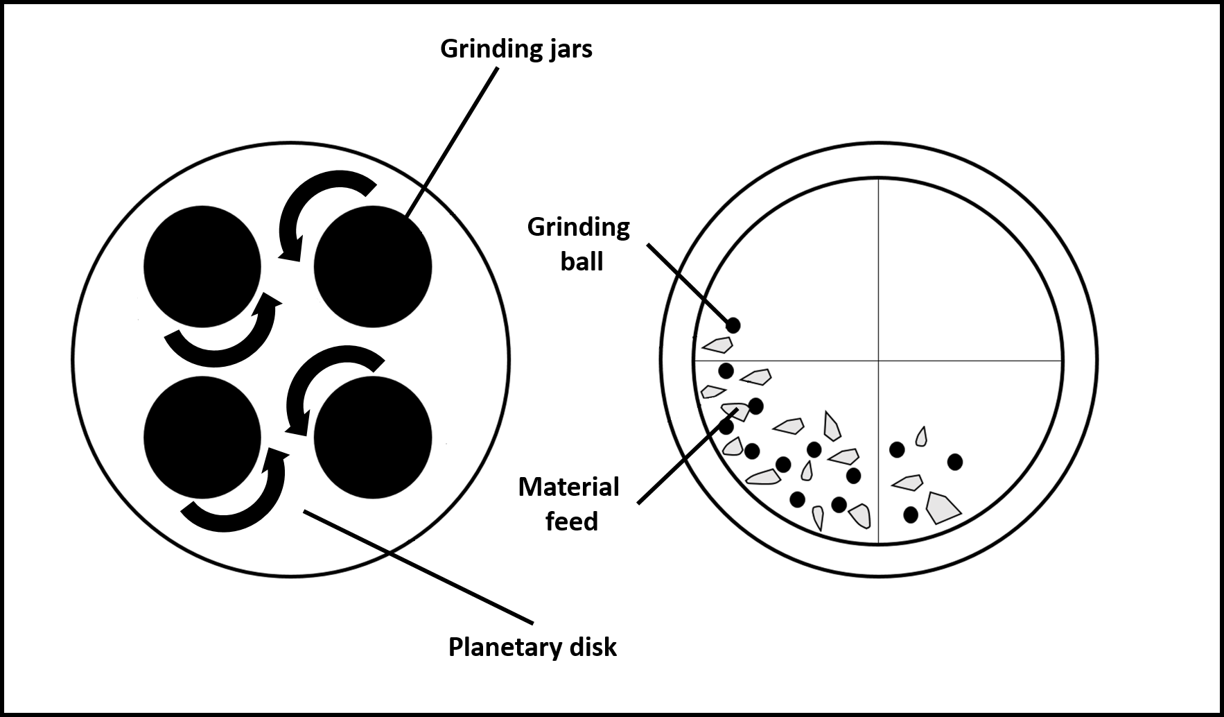
Planetary ball mills are often used for mechanical alloying because of small amounts of powder required and the machine is suitable for research purposes in a lab. A typical planetary ball mill consists of one planetary disk and two or four grinding jars. The disk and the jars rotate in opposite directions.
The grinding jar rotates on an orbit around the center and this movement produces centrifugal forces leading to strong grinding effects. Different rotational ratios are used to ground the material. With a rotation ratio of 1:2, the grinding jar rotates twice during the planetary disk turn.
Planetary ball mill employs grinding balls usually of size 10 to 30 mm depending on the powder particle size and impact energy required. If the balls are too small, the lower impact energy may not be sufficient for grinding. To increase the impact energy without increasing the rotational speed, high density balls made from tungsten may be employed.
-
Vibration mill
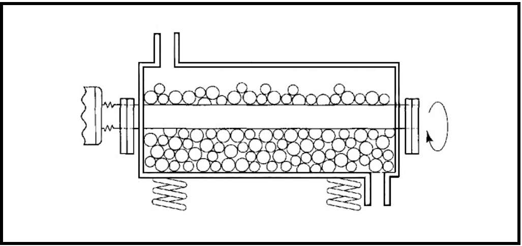
A vibration mill utilizes continuous impaction in carrying out size reduction of the feed material. The grinding container is in the shape of a tube that is held in a frame supported on springs. The tube is filled approximately 80% of total volume with porcelain or stainless steel balls.
Small frequent vibrations generated by an eccentric motor are imparted to the entire body during milling which results in grinding of the feed due to repeated impact. The vibrations imparted are usually, but not limited in vertical plane. Vibration mills are similar to ball mills in that feed is crushed between porcelain or metal balls and the mill body.
Vibration mills are especially suitable for hard abrasive grinding stocks, and these mills have much higher grinding rate and capacity compared to a conventional mill of the same size.
-
Colloidal mill
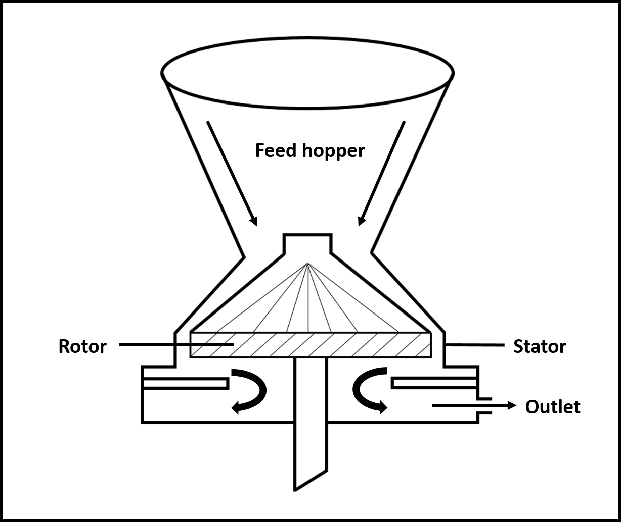
Colloidal suspensions, emulsions, and solid dispersions are produced utilizing colloidal mills or dispersion mills, and the droplets or particles of sizes less than 1 µm may be obtained.
The gap setting between the rotor and the stator is not directly proportional to the droplet size or the particle size. The material is continually passed between the working surfaces subjected to a high degree of shear and the energy absorbed within the feed sufficient to reduce the dispersed phase to particle size far smaller than the gap setting used.
The rotor speed varies with the physical size of the mill and the clearance necessary to achieve the desired results. All colloidal mills have high power consumption, and the material should, therefore, be grounded as finely as possible before it is fed to the mill.
Atomization:
In this method, high-pressure fluid jets break up a molten stream of metal/alloy into very fine droplets, which solidify into fine particles. High-quality powders of aluminum, iron, brass, stainless steel, tool steel, and superalloys can be manufactured commercially.The interaction between the fluid jet and liquid metal stream begins with the creation of small disturbances at the liquid surfaces, which grow into shearing forces that fragment the liquid into ligaments. The broken ligaments are further made to fine particles because of high energy in impact jet.
Atomization of molten metal can occur in different ways depending on required powder characteristics.-
Water atomization
High pressure water sprays are used to break the molten metal to produce fine metal powders or granules. To prevent oxidation of the powders, inert chambers are utilized which help in the production of high purity iron, copper, zinc and and powders. Water atomization produces irregular particles and the shape of the particle is dependent on the jet pressure and the angle of the jet to the molten metal stream. Particle sizes typically range from 30-1000 µm due to the rapid quenching. Water atomization is a cost effective process with high production rates. However, precautions must be taken as some metals/alloys may be reactive to water and additional steps must be implemented to remove water from the produced powder.
-
Gas atomization
Gas atomization can be performed in different ways depending on the atomization gas and the unit. This can be achieved either by air, or inert gas.Air atomization
Compressed air jets are used for the disintegration of the molten metal stream followed by cooling in chamber through large volumes of air. Powders produced through this method have relatively higher oxygen content.
, powder, and other powders used for hot isostatic pressing, metal injection molding, and brazing are produced using inert gas as it prevents oxidation. is produced from this process with sizes ranging from 30-200 µm for most metals. -
Centrifugal atomization
In this method, one end of the metal bar is heated and melted by bringing it into contact with a non-consumable tungsten electrode, while rotating it longitudinally at very high speeds. The centrifugal force created causes the metal drops to be thrown off outwards. The thrown off drops later solidify as inside an evacuated chamber. The powders produced exhibit high purity with the particle size ranging from 50-400 µm.
-
Rotating disk atomization
In this method, a stream of molten metal is impinged on to the surface of a rapidly spinning disk. This causes mechanical atomization of the metal stream and causes the droplets to be thrown off the edges of the disk. This method produces and the size decreases with increasing disk speed.
Electrodeposition:
The principle in this method is similar to electrolysis, during which a powder deposit is obtained on the cathode. The deposited powder is scrapped, washed, dried, and then further pulverized to get fine powder of the desired size. This method is primarily used for producing copper and iron powders along with other powders such as zinc, tin, nickel, cadmium, antimony, silver, lead, beryllium.Factors promoting electrolytic deposition are high current density, low metal concentration, pH of the bath, low temperature, high viscosity, circulation of electrolyte to avoid convection.
Electrolytic deposition produced powders of high purity with excellent sinterability, and a wide range of powder quality can be produced by altering the bath composition.
However, electrolytic deposition is a time-consuming process and results in other issues such as pollution of the workplace due to toxic chemicals, and their waste disposal is costly and difficult.
-
-
Mixing and blending
Mixing: When two powders of different chemistries such as elemental powder mixes or metal-nonmetal powders are combined, it is known as mixing. This process may be done in either dry or wet conditions. A liquid medium like alcohol, acetone, benzene, or distilled water are use milling medium in wet milling. Ball mills or rod mills are utilized for mixing hard metals such as carbides.
Blending: Process in which powders of the same compositions but with different sizes are intermingled. Blending is performed to obtain a uniform distribution of particles as porosity is reduced when powders consisting of various sizes are blended.
-
Compaction:
Pressure-less shaping techniques: These are used for the production of low-density and simple parts such as filters and other components that are porous. These techniques do not use any external force and depend on gravity for powder packing.
- Loose powder sintering
Loose powder sintering method is also known as loose powder shaping, gravity sintering, pressure-less sintering. In this method, a negative impression of the product is created in the mold, and the metal powder is mechanically vibrated into this mold, followed by heating to sintering temperature. This is the simplest method and involves low-cost equipment. However, this process is not widely used as it results in considerable shrinking during sintering, and after sintering, removing the object from the mold is very difficult.
, monel, and porous membranes are formed using loose powder sintering. - Vibratory compaction
Vibratory compaction uses vibration energy to compact the powder mass. During the process, small voids are filled with particles of still smaller sizes, and this sequence is carried out until a high packing density is achieved even before consolidation. The mechanical vibrations allow the formation of nearly closed packed powder by settling particles in the voids present in the agglomerated powder. This method is especially suited for brittle powders that develop cracks when subjected to pressure compaction. Vibratory compaction is generally employed when the powders have an irregular shape, the use of plasticizers is not desirable, and the sintered density is required to be identical to theoretical density.
Important Parameters
- Inertia of the system: Higher energy is required for packing for larger systems.
- Friction: Due to the frictional force between the particles, more kinetic energy is needed for compaction.
- Particle size distribution: Higher frequency is required for larger particles and the vibration cycle is important and not the duration of vibration.
Slip casting:
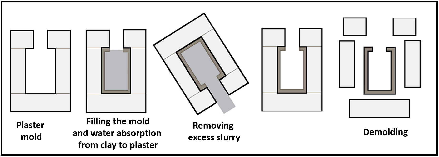
Slip casting is utilized for compacting metal and ceramic powders to produce large, complex shapes. A ‘slip’ can be defined as a suspension of metal or ceramic powder in a soluble liquid, which is poured into a mold, dried, and sintered.
Slip is usually made of a dispersion agent to stabilize the powder, a solvent to control slip viscosity and facilitate casting, a binder for providing green strength to the cast, and a plasticizer which modifies the properties of the binder.
Formation of an appropriate and consistent slip is necessary for a successful slip casting process, which is achieved by controlling the particle size, size distribution, and the order of component addition, their respective mixing time, and the addition of proper deflocculant.
Water is most widely used as the suspending medium in this process, but alcohol and other organic liquids can also be used. Additives like alginates, ammonium, and sodium salts of alginic acids serve three functions of deflocculant, suspension agent, and binding agent.
The cast obtained in the form of powder suspension in a suspending medium and the slip should have low viscosity and low rate of setting so that it can be readily poured. The slip-cast should be readily removable from the mold.
Steps involved in slip casting are preparation of assembled plaster mold, filling the mold, absorption of liquids from the slip into the mold, removal of the cast from the mold, and trimming of finished parts from the mold.Slip casting offers certain advantages as the process does not require expensive equipment, and the products that cannot be made from pressing can be made from slip casting. However, slip casting is a slow process and has limited applications commercially. Slip casting is used in the manufacturing of tubes, boats, crucibles, cones, turbine blades, rocket guidance fins.
Slurry casting:
- rechargeable batteries are produced by this method. In the next step, a portion of binder material is removed using solvent, thermal furnaces, catalytic processes, or a combination of these methods.Injection molding:
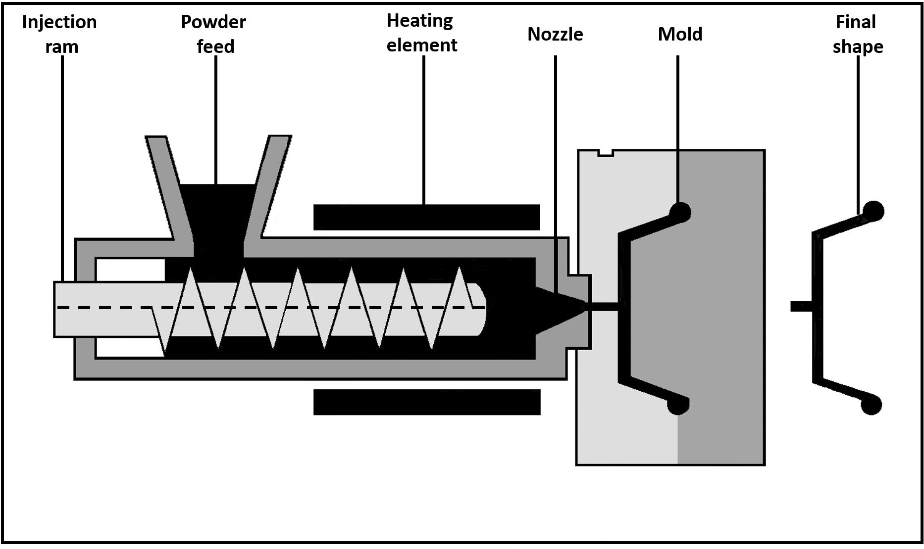
Metal Injection Molding (MIM) is a variation of traditional plastic injection molding that enables the fabrication of solid metal parts using injection molding technology. In this process, the raw material known as feedstock is a powder mixture of metal and polymer binders. For this reason, MIM is also referred to as Powder Injection Metallurgy (PIM).
MIM is best suited for the high-volume production of small metal parts, and these parts may be geometrically complex with fine details. As the process allows for the usage of metal powders, a wide variety of ferrous and non-ferrous alloys can be used. Also, as the powders are not melted in the process, high-temperature alloys can be used without any adverse effect on the tool life.
The first step in the MIM process is the preparation of feedstock. In this step, fine metal powders are combined with thermoplastic and wax binders in precise quantities. A homogeneous pelletized feedstock created by a compounding process can be injection molded, just like plastic. This achieves ultra-high density and close tolerances over high-production runs. Unlike standard powder metallurgy, which can achieve up to 80-90% of theoretical density, MIM results in 95-100% of theoretical density.
In the molding stage, the feedstock is heated and injected into a mold cavity under high pressure. This allows for producing extremely complex shapes in shorter cycle times. Once molded, the component is known as a green part. Its geometry is identical to the finished piece but is about 20% larger to allow for shrinkage during the sintering phase.
The third step is the debinding stage, where binder removal involves a controlled process to remove most of the binders and prepare the part for the final step – sintering. Once debinding is complete, the component is known as the brown part. Sintering is performed in the final stage to improve strength and eliminate remaining binders and porosity.
Metal parts manufactured from the MIM process are found in numerous industries, including aerospace, automotive, consumer products, medical/dental, and telecommunications. MIM components can be found in cell phones, sporting goods, power tools, surgical instruments, and various electronic and optical devices.
, high-speed steels, iron, , , , , and .Pressure shaping techniques: These techniques involve the application of external pressure to compact the loose powder particles, and the applied pressure can be unidirectional, bidirectional, or hydrostatic.
-
Die compaction
Die compaction is a forming technique involving the application of uniaxial compaction and shaping of powders with small amounts of water and/or organic binders during compression in a die. Compaction processes include dry pressing – where water content is less than 2% and semidry pressing, with 5-20% water. The compaction force can be applied by mechanical or hydraulic means. Pressure ranges up to several tens of megapascals, and the product sizes range from 1 mm to 100 mm in linear dimensions.
The critical step in die pressing is filling the die uniformly, and the small particles/agglomerates cause problems due to increasing particle-to-particle contact and the entrapment of air. For such fine powders, it is first necessary to granulate the fine particles into larger agglomerates to increase the flowability. The relevant properties of granulates used for die compaction are mean granule size, the density of granules, flow properties of granules, internal powder friction, and external powder-wall friction. Binders and lubricants are often used to improve the mentioned properties. Lubricants are often used to facilitate the uniform transmission of force and reduce friction during compaction, while binders are added to provide compact strength for subsequent handling.
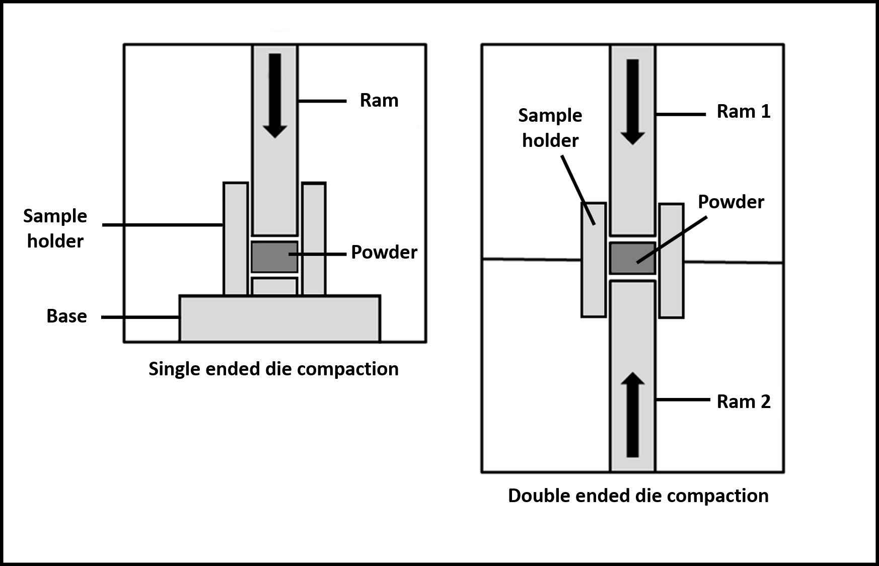
In general, the die compaction process is carried out in the following three steps – feeding of the powder or granulate into the die, compaction of the powder mass, and finally, the compact is ejected from the die.
In a single die compaction process, powders close to the punch and die walls experience better force than the center. This leads to density variations along the length of the sample. This non-uniformity can result in non-uniform properties of the sintered part.Density variations are significantly reduced in a double-ended die compaction process. In this method, the powder experiences uniform pressure from both the top and bottom, resulting in minimal density variations. However, components with a high aspect ratio still experience high-density variations. Hence, components such as long rods and tubes cannot be produced by die compaction method.
-
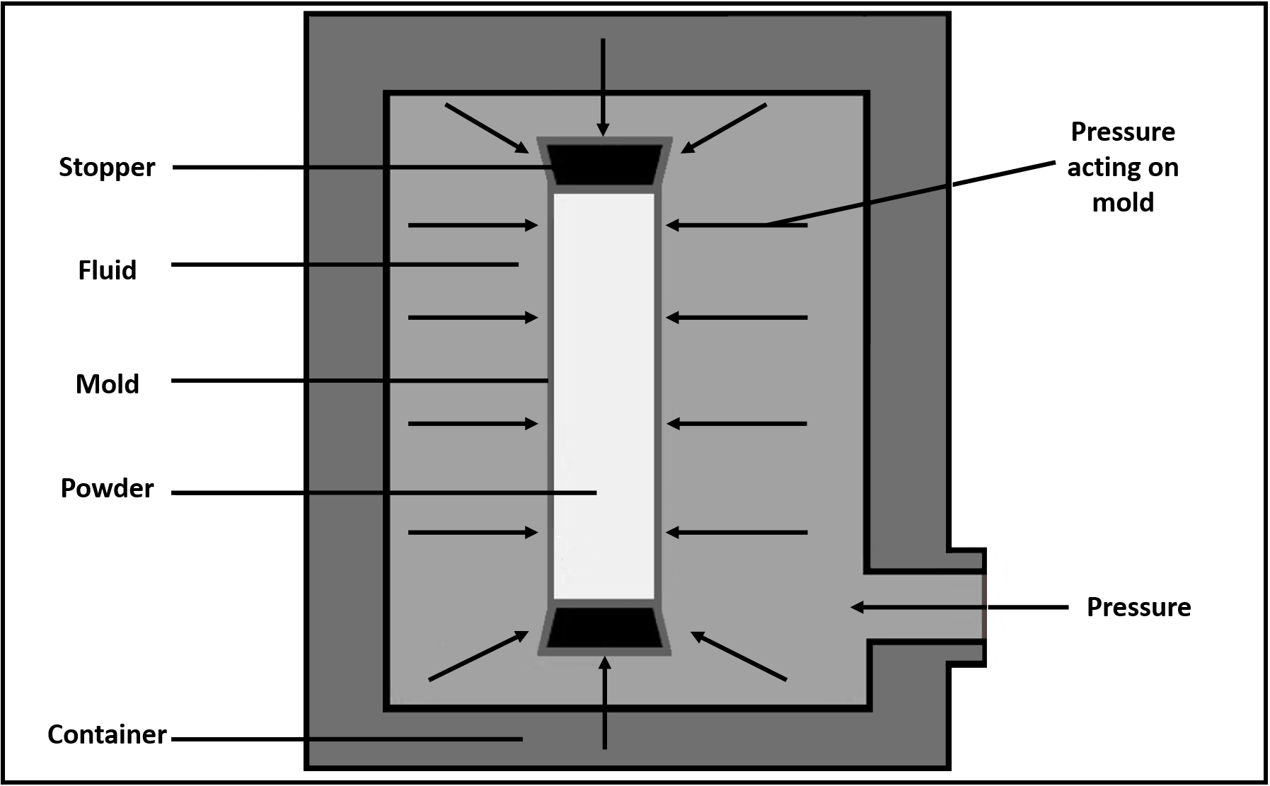
Isostatic pressing:
Hot Isostatic Pressing (HIP):
In this process, compaction is achieved by applying isostatic fluid pressure to a powder mass at room temperature, resulting in objects of desired shapes. Water or oil is usually used as the pressurizing medium, and the pressure is applied equally and simultaneously from all directions. The pressure applied ranges from 100-400 MPa. Sintered products can reach up to 97% of the theoretical density. Steps involved in cold isostatic pressing are – filling the mold with elemental or pre-alloyed powders, loading the mold into the press, pressurize the mold and hold, de-pressurize, and remove the mold, and remove compact sample and sinter.
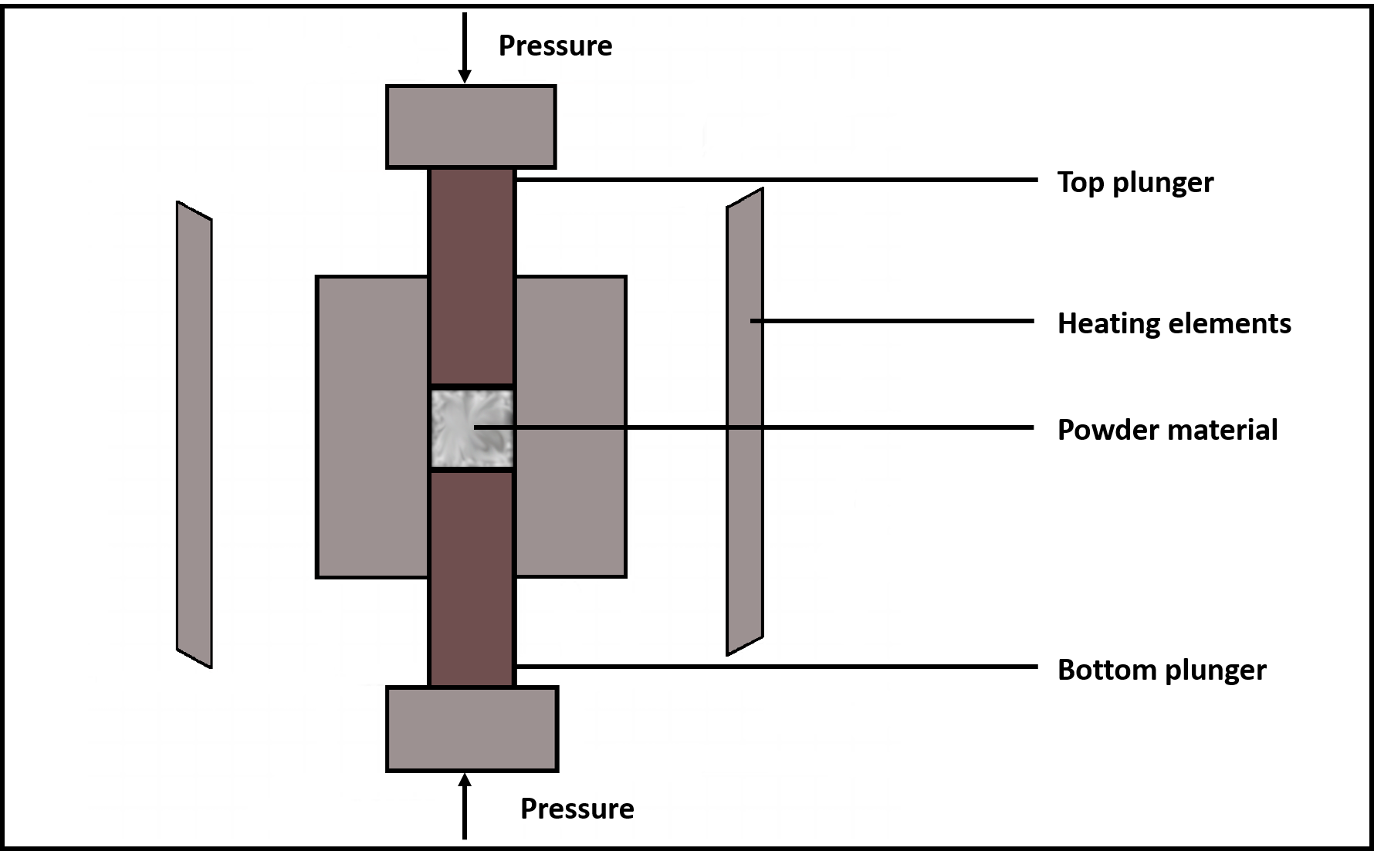
Hot isostatic pressing (HIP) is a manufacturing process used for reducing the porosity and increasing the densification of metal, ceramic and cermet powders with the application of pressure at elevated temperatures. The HIP unit consists of a pressure vessel, high-temperature furnace, pressurizing controls, and auxiliary systems (material handling, vacuum pumps, metering pumps).
and glass are also used for constructing the powder container.Once the container is filled with powder, the container is lowered into the system, and the system is vacuum pumped and sealed hermetically. The temperatures employed in HIP depend on the material powders, but usually, the temperature is in the range 1000-1200 OC. The furnace heats the powder container, while a pressurizing gas is let into the vessel, and the compressor is used to increase the pressure to the desired level. The application of high pressure at elevated temperatures results in densification due to plastic deformation, creep, and sintering.
The need for long-lasting, high-performance components exists in numerous manufacturing industries. The HIP is employed in major industries such as automotive, aerospace, military, heavy equipment manufacturing, industrial machinery, oil & gas, marine, and medical.
, high-steels, , and , , carbide, advanced ceramics, and composite materials.
Important parameters
- Container materials
Container materials and thickness are important parameters and must satisfy certain conditions. Firstly, the container must be strong enough to maintain shape and dimensions prior to and during the isostatic pressing. Secondly, the material must be soft, malleable at elevated temperatures, and it must be compatible with the powder being processed. It must not penetrate and react with the powder mass. Also, the container must be leakproof at high pressures. - Container shrinkage
The container shrinkage is not isostatic during the process, and it depends on parameters such as container material, geometry, thickness, container positioning, and powder fill density within the container.
Benefits of HIP
- Densification of powdered metal parts to values close to theoretical density (~98-99%).
- Complete elimination of internal porosity in the castings.
- HIP results in highly efficient production as near net shapes are formed to precise tolerances with little or no secondary machining along with reduction in scrap loss.
- The HIP can also provide cost-effective diffusion bonding (cladding) of dissimilar metals.
Cold Isostatic Pressing (CIP) is used to produce complex parts with very high consistency and uniform density, that is otherwise impossible to produce by other conventional methods.
An isostatic pressure reproduces the conditions found several thousand feet below the surface of the ocean in compressing any object placed within it.
In an isostatic press, hydraulic pressure is generated by pumps, and this pressure can be controlled accurately. A flexible mold designed to form an article is placed at the center of isostatic pressure. A membrane is used to keep the flexible mold dry, and this assembly is contained within the pressure vessel. Two sealing caps, one at top and the other at the bottom, are positioned to retain the mold assembly securely in the vertical plane. A measured amount of powder is fed into the mold cavity over the bottom cap, and when the cavity has been filled, the top cap comes into place to seal it.
The fluid is pumped around a flexible mold assembly and is pressurized. Water or oil is usually used as the pressurizing medium, and applied pressure ranges from 100-400 MPa. As the pressure increases, the loose powder is compacted into a solid shape. The amount of compaction depends on the amount of pressure applied and the material powder used. After the compaction, the pressure is released in a controlled manner. The speed of decompression is changed to suit different materials and compacted shapes. The loose, free-flowing powder is now a solid shaped compact with a uniform density throughout. The flexible mold moves away from the compacted part and resumes its original shape, ready for the next cycle. When the pressure is zero, and the bag has totally regained its shape, the contact can be removed. The top tool is moved upwards in preparation for the next fill of powder, and the bottom tool is moved downward, taking the compact with it, and the compact can be removed from the tooling before it returns to the pressure vessel for the next cycle.
Important parameters
Powder flow: The powder flow is an essential characteristic of this process. The powder must be able to flow quickly and evenly into the cavity. If it does not, the compact will have inconsistent weight and dimensions. If the powder clogs or bridges on the way into the cavity, no contact will be produced. Different size powders compact in different amounts resulting in different sized components. Depending on the natural characteristics of the powder, there may be a need to add binding agents to increase the components strength after pressing.
Applications of CIP: Hydraulic aircraft fittings using titanium powder and aluminum-vanadium master alloy powder, high-speed tool steels, compacts with internal threads, long hollow cylinder filters, and tungsten and molybdenum slabs for further forging or/and rolling.
Benefits of CIP
- Programmable pressure distribution with good accuracy and reduced mechanical stresses of processed materials.
- The ability to process large, complicated, and near-net shapes, saves time and cost during secondary machining processes.
- Capability to produce large aspect ratios (2:1) with uniform densities.
- Green strength allows in-process handling and treatment and lowers the production cost.
- Container materials
-
Powder rolling:
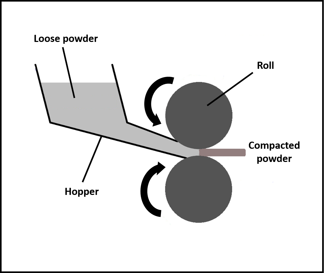
Elemental or alloyed powders are fed between two rolls to produce a coherent and brittle greens strip. This green strip is sintered and re-rolled to obtain a dense, finished product. Steps involved in powder rolling are – preparation of green strip, sintering, densification of the sintered strip, and final cold rolling and annealing. Parameters affecting powder rolling are roll gap (larger role gap leads to reduced green density, whereas very small roll gap leads to edge cracking), roll diameter (increase in diameter increases density and strength), roll speed (kept low around 0.3-0.5 m/s) and powder characteristics (irregular powder with rough surfaces provide better strip density).
-
Explosive compaction:
Explosive forming involves shaping metal parts in dies by using an explosive charge to generate forming pressure or shaping metals using explosions. Explosive forming techniques can be divided into two groups, depending on the position of the explosive charge relative to the workpiece. In the standoff method, the metal plate is placed over a die, with the intervening space evacuated by a vacuum pump, then the whole assembly is placed underwater, and explosive material is placed at an appropriate height above the plate. For complicated shapes, a segmented die can be used. In the contact method, the explosive charge is held in direct contact with the workpiece while the detonation is initiated. The detonation produces very high interface pressures on the surface of the metal.
-
- Loose powder sintering
Sintering
Sintering is the process of heating the powder compact to elevated temperatures but below their melting point such that powder particles coalesce into a solid due to diffusion, not due to melting. Sintering is performed in order to impart strength and integrity to the powder compact, to remove porosity, and to increase the degree of densification.The kinetics of the sintering process is split into three stages:
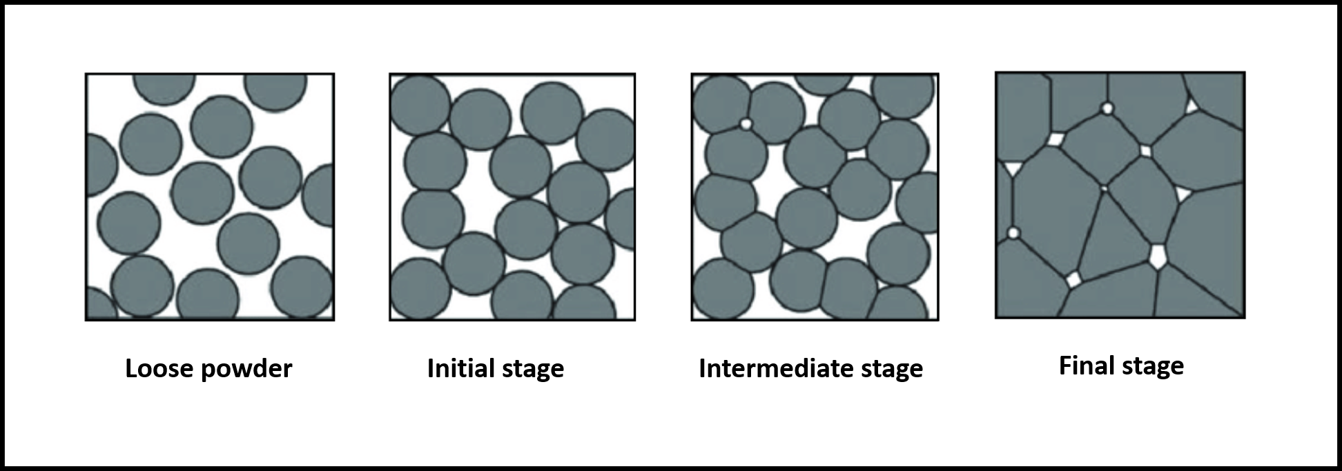
Initial Stage
Initially, the particles that are in contact form grain boundaries at the point of contact due to diffusion, and the increase in the initial density of compaction results in a higher degree of coherency in the material. In this stage, necks begin to form at the point of contact between two adjacent particles, and therefore, this stage is referred to as neck growth stage. There are no changes observed in dimensions in this stage, and the porosity also does not decrease. The driving force for the neck formation is the energy gradient resulting from different curvatures of the particles and the neck. In the initial stages, surface diffusion is usually the dominant mass-transport mechanism, as the compact is heated to the sintering temperature.
Intermediate Stage
In this stage, adjacent necks begin to impinge on each other, resulting in densification and grain growth. The packing density of the green packing is critical as high packing density produces relatively few pores in the final object. The intermediate stage results in pore channel closure, where interconnected pore charnels are closed off isolating porosity. Pore channel closure occurs due to neck growth and due to the formation of new contact points by pore shrinkage. Initially, the pores form a network of interconnected cylindrical pores broken up by necks. As the process continues, the pores are smoother and become isolated from each other. In the intermediate stages, bulk transport mechanisms such as grain boundary diffusion and volume diffusion, dominate the sintering process.
Final Stage
In this stage, most of the pores are closed. As sintering proceeds, the pores which formed a network in the intermediate stage, are isolated from each other. The third stage is the slowest stage of sintering. The pores break away from the grain boundaries and become spherical as the grain size increases. Pore shrinkage is the most crucial stage in sintering, and in this stage, solids are transported into the pores, and the gas in the pores escape to the surface. As a result, there is a decrease in the volume of the sintering mass, and smaller pores are eliminated, whereas the larger pores might shrink or grow. In some cases, pore growth during the final stage of sintering leads to a decrease in density because gas pressure in the larger pores inhibits further densification.